Wiring a 5 pin rocker switch for a light bar might seem complex, but it’s manageable with the correct guidance; at rockscapes.net, we simplify the process, ensuring you connect your light bar effectively. We help you illuminate your path and enhance your vehicle’s functionality by providing detailed instructions, safety tips, and resources for selecting the right rocker switch. With our expertise, you’ll master auxiliary lighting installation, electrical connections, and switch illumination using durable components and innovative solutions.
1. What Is a 5 Pin Rocker Switch and Why Use It?
A 5 pin rocker switch is an electrical switch used to control the flow of electricity to a device, often featuring two independent circuits, making it ideal for controlling light bars with added functionality like backlighting. Its popularity stems from its rectangular shape, blending well with vehicle interiors, and its illuminated light indicators that show when the light bar is on.
The 5 pin rocker switch is a versatile component commonly used in automotive and other applications for controlling electrical circuits. This type of switch stands out due to its five pins, each serving a specific function, which allows for more complex wiring configurations compared to simpler switches. The primary reason for its widespread use is the added control and feedback it provides to the user. These switches often include independent circuits, making them perfect for controlling light bars along with additional features such as backlighting or indicator lights. This allows the user to not only control the light bar but also to visually confirm its status, enhancing the user experience.
Enhanced Functionality and Aesthetics
One of the main reasons the 5 pin rocker switch is popular is its aesthetic appeal and functional design. Its rectangular shape typically blends seamlessly with the interior of most vehicles, providing a clean and professional look. Moreover, the switch includes illuminated lights that can be wired to work with the vehicle’s factory interior dash lighting. This feature ensures that the switch is visible in low-light conditions and provides a visual indication of the switch’s status. There are usually two lights on a 5 pin rocker switch. When the light bar is activated, one light illuminates, clearly indicating that the light bar is powered on. This is particularly useful for preventing the light bar from being left on accidentally, which could drain the vehicle’s battery or cause glare to oncoming traffic.
Versatile Applications
The versatility of the 5 pin rocker switch makes it suitable for a wide range of applications beyond just light bars. It can be used to control various auxiliary lights, fog lights, driving lights, and other electrical accessories in vehicles. Its ability to handle two independent circuits also makes it useful in controlling more complex systems where multiple functions need to be managed with a single switch. This makes it a favorite among DIY enthusiasts and professional installers alike.
Understanding the Switch
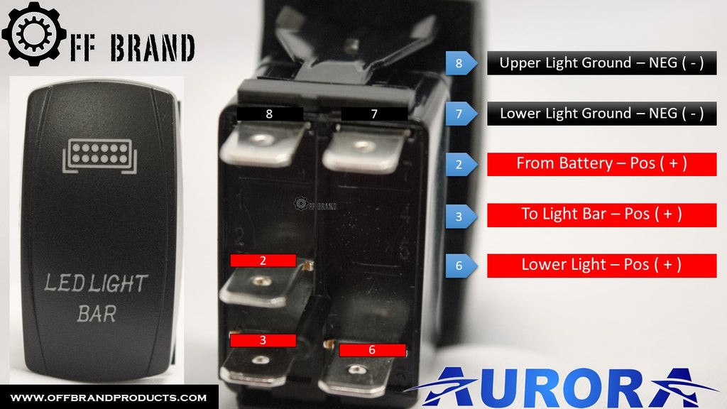
To fully appreciate the benefits of using a 5 pin rocker switch, it is important to understand the function of each pin. Typically, the pins are arranged in a specific order on the back of the switch, and each pin serves a unique purpose:
- Pin 1 (or #8): Ground for the upper light in the switch. This pin is responsible for grounding the LED that illuminates when the light bar is active.
- Pin 2 (or #7): Ground for the lower light in the switch. This pin grounds the LED that lights up when the vehicle’s dashboard lights are on, allowing the switch to be visible at night.
- Pin 3 (or #2): Positive power input from the battery or a fused power source. This pin provides the main power supply to the switch.
- Pin 4 (or #3): Positive power output to the light bar. This pin connects directly to the light bar, supplying it with power when the switch is activated.
- Pin 5 (or #6): Positive power input to the lower light in the switch. This pin powers the LED that illuminates with the dashboard lights.
By understanding these functions, users can effectively wire the switch to achieve the desired lighting and control configurations.
Why Choose a 5 Pin Rocker Switch?
In summary, the 5 pin rocker switch is a popular choice for controlling light bars and other automotive accessories due to its enhanced functionality, aesthetic design, and versatility. Its ability to provide visual feedback through illuminated lights and manage multiple circuits makes it a superior option compared to simpler switches. Whether you are a seasoned DIYer or a professional installer, the 5 pin rocker switch offers a reliable and efficient solution for managing your vehicle’s electrical accessories. At rockscapes.net, we provide detailed guides and resources to help you make the most of this versatile switch, ensuring your installations are safe, effective, and visually appealing.
2. What Are the Legal Considerations for Light Bar Switches?
Legal considerations for light bar switches vary by state, requiring illuminated switches when the light is on to ensure drivers know when auxiliary lights are active and avoid blinding oncoming traffic. It’s crucial to know and comply with local regulations.
Installing aftermarket auxiliary lighting on vehicles requires careful consideration of state and local laws to ensure compliance and safety. Regulations can vary significantly, and being aware of these rules is crucial for avoiding legal issues and ensuring responsible use of additional lighting. For example, many states have specific requirements regarding the use of light bars on public roads, including restrictions on brightness, color, and mounting height. Understanding these regulations helps ensure that your installation is both legal and safe for yourself and other drivers.
Illumination Requirements
One common legal requirement is the need for an illuminated switch that indicates when the light bar is active. This regulation is in place to ensure that drivers are aware when their auxiliary lights are turned on, preventing accidental blinding of oncoming traffic. For instance, in Pennsylvania, an illuminated switch is mandatory for light bars to ensure drivers are continuously reminded when the auxiliary light is in use. This helps prevent misuse and enhances road safety.
Color and Brightness Restrictions
Many jurisdictions also have rules regarding the color and brightness of auxiliary lights. Some states restrict the use of certain colors, such as blue or red, which are typically reserved for emergency vehicles. Additionally, there may be limits on the maximum brightness (measured in lumens) allowed for auxiliary lights to prevent excessive glare. Compliance with these regulations ensures that your lighting setup does not impair the vision of other drivers.
Mounting Height and Placement
The mounting height and placement of light bars are often regulated to minimize glare and ensure proper visibility. Some states have specific rules about how high or low auxiliary lights can be mounted on a vehicle. Proper placement ensures that the lights function effectively without creating hazards for other drivers.
When and Where Light Bars Can Be Used
In addition to the technical specifications of the lights themselves, there are often regulations about when and where light bars can be used. Many states prohibit the use of light bars on public roads under normal driving conditions, restricting their use to off-road situations or specific emergency scenarios. It’s important to understand these restrictions to avoid fines or other penalties.
Staying Compliant
To ensure compliance with local laws, it’s advisable to research the specific regulations in your state or region before installing a light bar. Websites, automotive forums, and local law enforcement agencies can provide detailed information on lighting regulations. Additionally, consulting with a professional installer can help ensure that your setup meets all legal requirements.
Resources
Several resources are available to help vehicle owners stay informed about lighting regulations:
- State Department of Motor Vehicles (DMV): The DMV website for your state is a primary source for vehicle equipment regulations, including those related to auxiliary lighting.
- Local Law Enforcement Agencies: Local police departments and sheriff’s offices can provide clarification on specific regulations in your area.
- Automotive Forums and Clubs: Online forums and automotive clubs often have discussions and resources related to vehicle lighting laws.
- Professional Installers: Certified automotive technicians who specialize in aftermarket lighting installations can ensure your setup complies with all applicable laws.
By staying informed and proactive, you can enjoy the benefits of auxiliary lighting while remaining within the bounds of the law. At rockscapes.net, we encourage our customers to prioritize safety and legal compliance when installing and using light bars. We offer resources and guidance to help you make informed decisions and ensure your lighting setup is both effective and legal.
3. How to Identify the Pins on a 5 Pin Rocker Switch?
Identifying the pins on a 5 pin rocker switch involves recognizing each pin’s function: two grounds (one for each light), positive power input, positive power output to the light bar, and positive power to the lower light. Knowing these ensures correct wiring.
To effectively wire a 5 pin rocker switch, it is essential to understand the function of each pin. These switches come with five terminals on the back, each serving a specific purpose. Correctly identifying these pins ensures that the switch operates as intended, providing the desired control and illumination. Let’s break down the function of each pin to guide you through the wiring process.
Pin Arrangement and Function
Typically, the pins on a 5 pin rocker switch are arranged in a specific order. When the switch is held upright, the pins are numbered or labeled from top to bottom. Here’s a detailed look at each pin:
-
Pin #8: Ground for the Upper Light
- Function: This pin is the ground connection for the LED that illuminates when the light bar is active. It completes the circuit, allowing the upper light to turn on when the switch is engaged.
- Wiring Tip: This terminal can be grounded together with Pin #7 for convenience.
-
Pin #7: Ground for the Lower Light
- Function: This pin is the ground connection for the lower LED light, which typically illuminates when the vehicle’s dashboard lights are on. This allows the switch to be visible in low-light conditions.
- Wiring Tip: This terminal can usually be grounded with Pin #8, unless you are wiring the switch lights with your vehicle’s factory light dimmer. In that case, it needs a separate ground.
-
Pin #2: Positive Power Input
- Function: This pin receives the positive power from the battery or a fused power source. It provides the main power supply to the switch.
- Wiring Tip: This terminal can be combined with Pin #6 to simplify the wiring process.
-
Pin #3: Positive Power Output to Light Bar
- Function: This pin sends the positive power to the light bar. When the switch is activated, power flows through this pin to turn on the light bar.
- Wiring Tip: This is the only terminal that cannot be combined with another terminal. It must have a direct connection to the light bar.
-
Pin #6: Positive Power to Lower Light
- Function: This pin provides the positive power to the lower light in the switch. This LED illuminates with the dashboard lights, ensuring the switch is visible at night.
- Wiring Tip: This terminal can be combined with Pin #2 for easier wiring.
Visual Aids and Markings
Most 5 pin rocker switches have markings or symbols near each pin to indicate their function. These markings can include numbers, letters, or symbols that correspond to the pin’s role. Common symbols include:
- Ground Symbol: Often a small, horizontal line connected to a vertical line.
- Positive Symbol: A plus sign (+).
- Light Bulb Symbol: Indicates a connection to an LED light.
Refer to the switch’s diagram to accurately identify each pin.
Testing with a Multimeter
If the markings are unclear or absent, a multimeter can be used to identify each pin. Here’s how:
- Set the Multimeter: Set the multimeter to the continuity testing mode.
- Identify Ground Pins: Connect one probe to a known ground (such as the vehicle’s chassis) and touch the other probe to each pin. The multimeter will beep or show continuity when connected to a ground pin (Pin #7 or #8).
- Identify Power Input and Output Pins: Connect the multimeter to a power source and test each pin to determine which ones receive power when the switch is in different positions (on or off).
Common Mistakes to Avoid
- Incorrect Grounding: Ensure that the ground connections are secure and properly connected to the vehicle’s chassis. Poor grounding can cause the switch to malfunction or damage the electrical system.
- Overloading the Switch: Do not connect the switch to a light bar that exceeds its rated current capacity. Overloading the switch can cause it to overheat and fail.
- Mixing Up Input and Output Pins: Double-check that the positive power input (Pin #2) and the positive power output (Pin #3) are correctly identified to avoid damaging the switch or the light bar.
Practical Tips for Easy Identification
- Keep the Switch Diagram Handy: Always have the switch’s wiring diagram nearby for reference.
- Use Color-Coded Wires: Use different colored wires for each connection to easily track which wire goes to which pin.
- Label Each Wire: Label each wire with a piece of tape indicating which pin it connects to.
- Take Photos: Take photos of the wiring process as you go, so you have a visual reference if you need to troubleshoot later.
Accurately identifying the pins on a 5 pin rocker switch is crucial for a successful and safe installation. By understanding the function of each pin and using the tips provided, you can confidently wire the switch and enjoy the enhanced functionality of your light bar. At rockscapes.net, we emphasize the importance of proper wiring and provide the resources you need to get the job done right.
 Wiring harness with 5 pin rocker switch
4. What Tools and Materials Do You Need to Wire a 5 Pin Rocker Switch?
Wiring a 5 pin rocker switch requires tools such as wire strippers, crimpers, a multimeter, and materials like wire, connectors, and a fuse. These ensure a safe and reliable connection for your light bar.
To properly wire a 5 pin rocker switch for your light bar, it’s important to gather all the necessary tools and materials. Having the right equipment not only makes the job easier but also ensures a safe and reliable connection. Here’s a comprehensive list of what you’ll need:
Essential Tools
-
Wire Strippers:
- Purpose: To remove the insulation from the wires without damaging the conductive core.
- Features to Look For: Adjustable gauge settings to accommodate different wire sizes, comfortable grip, and sharp blades for clean stripping.
-
Wire Crimpers:
- Purpose: To securely attach connectors to the ends of the wires.
- Features to Look For: Ratcheting mechanism for consistent crimps, interchangeable dies for different connector types, and ergonomic handles.
-
Multimeter:
- Purpose: To test the voltage, current, and continuity of the electrical connections.
- Features to Look For: Digital display for accurate readings, auto-ranging capability, and built-in continuity tester.
-
Pliers:
- Purpose: To grip, bend, and manipulate wires.
- Types: Needle-nose pliers for tight spaces, and regular pliers for general use.
-
Screwdrivers:
- Purpose: To tighten and loosen screws on the switch and other components.
- Types: Phillips head and flathead screwdrivers in various sizes.
-
Electrical Tape:
- Purpose: To insulate and protect exposed wires and connections.
- Features to Look For: High-quality, flame-retardant tape that provides a secure seal.
-
Heat Gun or Lighter:
- Purpose: To shrink heat shrink tubing for a secure and insulated connection.
- Safety Note: Use with caution to avoid burns or damage to the surrounding components.
-
Drill (Optional):
- Purpose: To create mounting holes for the switch if necessary.
- Features to Look For: Cordless drill with adjustable speed settings and a set of drill bits.
Essential Materials
-
Wires:
- Type: Stranded copper wire is recommended for automotive applications due to its flexibility and durability.
- Gauge: Typically, 16-gauge or 18-gauge wire is suitable for light bar switches, but check the light bar’s specifications for the appropriate wire size.
- Colors: Use different colored wires to easily distinguish between the different connections (e.g., red for positive, black for ground).
-
Connectors:
- Types: Spade connectors, ring connectors, and butt connectors.
- Purpose: To create secure and reliable connections between the wires and the switch, light bar, and power source.
- Features to Look For: Insulated connectors for added protection, and corrosion-resistant materials for durability.
-
Fuse and Fuse Holder:
- Purpose: To protect the electrical circuit from overloads and short circuits.
- Rating: Choose a fuse with an amperage rating that matches the light bar’s requirements.
- Placement: Install the fuse holder as close as possible to the power source.
-
Heat Shrink Tubing:
- Purpose: To provide insulation and protection for the wire connections.
- Sizes: Various sizes to fit different wire gauges.
- Features to Look For: Adhesive-lined tubing for a waterproof seal.
-
Zip Ties:
- Purpose: To bundle and secure the wires, keeping them organized and out of the way.
- Features to Look For: UV-resistant zip ties for durability in outdoor environments.
-
Rocker Switch:
- Type: A 5 pin rocker switch designed for light bar applications.
- Features to Look For: Illuminated LEDs, durable construction, and appropriate voltage and current ratings.
Additional Supplies
- Safety Glasses: To protect your eyes from debris.
- Work Gloves: To protect your hands and improve grip.
- Wire Labels: To label each wire for easy identification.
- Shop Rags: To clean up any spills or messes.
Tips for Gathering Your Supplies
- Check the Light Bar’s Specifications: Before purchasing wires and fuses, check the light bar’s specifications for the recommended wire gauge and fuse amperage.
- Buy Quality Components: Invest in high-quality tools and materials to ensure a reliable and long-lasting connection.
- Organize Your Supplies: Keep your tools and materials organized in a toolbox or workstation for easy access.
- Consider a Wiring Kit: Many automotive retailers offer wiring kits specifically designed for light bars, which include all the necessary components.
Having the right tools and materials on hand will make the wiring process smoother and safer. At rockscapes.net, we recommend taking the time to gather everything you need before starting the project. This will help you avoid frustration and ensure a professional-quality installation.
5. How Do You Create Jumper Cables for a 5 Pin Rocker Switch?
Creating jumper cables for a 5 pin rocker switch involves connecting ground pins and positive power input pins to simplify wiring. These jumper cables streamline the installation process and ensure efficient power distribution.
Creating jumper cables for a 5 pin rocker switch is a practical way to simplify the wiring process. These cables allow you to connect multiple pins together, reducing the number of individual wires needed and making the overall installation cleaner and more organized. Here’s a step-by-step guide on how to create jumper cables for your 5 pin rocker switch.
Understanding Jumper Cables
Jumper cables are short lengths of wire used to connect two or more electrical terminals. In the context of a 5 pin rocker switch, they are typically used to connect the ground pins and the positive power input pins. This simplifies the wiring by allowing you to power multiple functions from a single source or ground them to a single point.
Materials Needed
-
Wire:
- Type: Stranded copper wire (16-gauge or 18-gauge).
- Color: Use different colors to differentiate between ground and power connections.
-
Connectors:
- Types: Spade connectors or fork connectors.
- Size: Match the size of the pins on the rocker switch.
-
Wire Strippers:
- Purpose: To remove insulation from the wires.
-
Wire Crimpers:
- Purpose: To securely attach the connectors to the wires.
-
Heat Shrink Tubing:
- Purpose: To insulate and protect the connections.
-
Heat Gun or Lighter:
- Purpose: To shrink the heat shrink tubing.
-
Scissors or Wire Cutters:
- Purpose: To cut the wires to the desired length.
Step-by-Step Instructions
-
Measure and Cut the Wires:
- Determine the length of the jumper cables needed to connect the pins on the rocker switch. Typically, a few inches of wire is sufficient.
- Use wire cutters to cut the wires to the desired length.
-
Strip the Wire Ends:
- Use wire strippers to carefully remove about 1/4 to 1/2 inch of insulation from both ends of each wire.
- Be careful not to nick or damage the copper strands.
-
Attach the Connectors:
- Insert one end of the stripped wire into a spade or fork connector.
- Use wire crimpers to securely crimp the connector onto the wire. Ensure the connection is tight and the wire is firmly held in place.
- Repeat this process for the other end of the wire.
-
Apply Heat Shrink Tubing:
- Slide a piece of heat shrink tubing over each connector, ensuring it covers the crimped connection.
- Use a heat gun or lighter to carefully shrink the tubing. Apply heat evenly until the tubing tightly conforms to the connector and wire.
- This provides insulation and protection for the connection, preventing shorts and corrosion.
-
Create Jumper Cables for Ground Connections:
- Typically, pins #7 and #8 are grounded together. Create a jumper cable to connect these two pins.
- Follow the steps above to cut, strip, crimp, and insulate the wire.
-
Create Jumper Cables for Positive Power Connections:
- Typically, pins #2 and #6 are connected for positive power input. Create a jumper cable to connect these two pins.
- Follow the same steps to prepare the wire and attach the connectors.
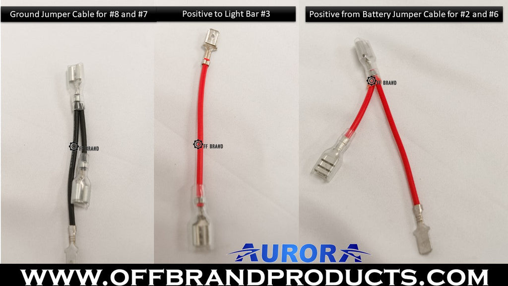
Wiring Diagram
Here’s a simple wiring diagram to illustrate how the jumper cables are used:
- Ground Jumper Cable:
- Connect one end to Pin #7 (Ground for the Lower Light).
- Connect the other end to Pin #8 (Ground for the Upper Light).
- Positive Power Jumper Cable:
- Connect one end to Pin #2 (Positive Power Input).
- Connect the other end to Pin #6 (Positive Power to Lower Light).
Tips for Success
- Use Different Colored Wires: To easily distinguish between ground and power connections, use different colored wires. For example, use black wire for ground connections and red wire for power connections.
- Ensure Secure Connections: Double-check that all connectors are securely crimped and that the heat shrink tubing is properly applied. Loose connections can cause the switch to malfunction or create a fire hazard.
- Label the Wires: Use wire labels or a permanent marker to label each jumper cable with its function (e.g., “Ground Jumper” or “Power Jumper”).
- Test the Connections: Before installing the switch, use a multimeter to test the continuity of each jumper cable. This ensures that the connections are good and that there are no shorts.
Benefits of Using Jumper Cables
- Simplified Wiring: Reduces the number of individual wires needed, making the wiring process easier and less cluttered.
- Organized Installation: Helps keep the wiring organized and tidy, improving the overall appearance and functionality of the installation.
- Reliable Connections: Ensures secure and reliable connections between the pins, reducing the risk of loose connections and electrical problems.
Creating jumper cables for your 5 pin rocker switch is a simple yet effective way to streamline the wiring process. By following these steps and using the right tools and materials, you can create professional-quality jumper cables that will enhance the performance and reliability of your light bar installation. At rockscapes.net, we provide detailed guides and resources to help you with all your wiring needs, ensuring a safe and successful project.
 Jumper cables connected to 5 pin rocker switch
6. What Are the Step-by-Step Instructions for Wiring a 5 Pin Rocker Switch?
Wiring a 5 pin rocker switch involves connecting ground wires, positive power input, and power output to the light bar. This ensures proper illumination and functionality.
Wiring a 5 pin rocker switch can seem daunting at first, but with a clear understanding of each pin’s function and a step-by-step approach, you can complete the task efficiently and safely. This guide provides detailed instructions on how to wire a 5 pin rocker switch for your light bar, ensuring proper illumination and functionality.
Step 1: Gather Your Tools and Materials
Before you begin, make sure you have all the necessary tools and materials on hand. Refer to Section 4 for a complete list of tools and materials.
Step 2: Prepare the Wires
-
Measure and Cut the Wires:
- Determine the length of wire needed to reach from the switch to the power source, ground, and light bar.
- Use wire cutters to cut the wires to the appropriate lengths.
-
Strip the Wire Ends:
- Use wire strippers to carefully remove about 1/4 to 1/2 inch of insulation from each wire end.
- Be careful not to nick or damage the copper strands.
-
Attach Connectors:
- Attach spade or fork connectors to the wire ends that will connect to the switch, power source, ground, and light bar.
- Use wire crimpers to securely crimp the connectors onto the wires.
Step 3: Connect the Ground Wires (Pins #7 and #8)
-
Identify the Ground Pins:
- Locate pins #7 and #8 on the back of the rocker switch. These are the ground connections for the lower and upper lights, respectively.
-
Connect the Jumper Cable (Optional):
- If you have created a jumper cable for the ground connections, connect one end to pin #7 and the other end to pin #8.
-
Connect to Ground:
- Connect the other end of the ground wire (or the jumper cable) to a suitable ground point on the vehicle’s chassis. Ensure the ground point is clean and free of paint or rust for a good electrical connection.
Step 4: Connect the Positive Power Input (Pin #2)
-
Identify the Positive Power Input Pin:
- Locate pin #2 on the back of the rocker switch. This is the main power input for the switch.
-
Connect to Power Source:
- Connect a wire from pin #2 to a fused power source. This can be the vehicle’s battery or an auxiliary power distribution block.
- Ensure the fuse is properly rated for the light bar’s power requirements.
Step 5: Connect the Positive Power to Lower Light (Pin #6)
-
Identify the Positive Power Pin:
- Locate pin #6 on the back of the rocker switch. This provides power to the lower light.
-
Connect to Power Source:
- Connect a wire from pin #6 to the same fused power source as pin #2. This allows the lower light to illuminate when the vehicle is on.
Step 6: Connect the Positive Power Output to Light Bar (Pin #3)
-
Identify the Positive Power Output Pin:
- Locate pin #3 on the back of the rocker switch. This is the power output that will activate the light bar.
-
Connect to Light Bar:
- Connect a wire from pin #3 to the positive wire on the light bar.
Step 7: Test the Connections
-
Inspect the Wiring:
- Double-check all the connections to ensure they are secure and properly connected to the correct pins.
-
Test with a Multimeter:
- Use a multimeter to test the continuity of the connections and ensure there are no shorts or open circuits.
-
Activate the Switch:
- Turn on the power source and activate the rocker switch. The light bar should illuminate, and the LEDs on the switch should light up.
Step 8: Secure and Organize the Wiring
-
Use Zip Ties:
- Use zip ties to bundle and secure the wires, keeping them organized and out of the way.
-
Protect the Wires:
- Use heat shrink tubing or electrical tape to protect any exposed connections.
-
Mount the Switch:
- Mount the rocker switch in a convenient and accessible location in the vehicle.
Wiring Diagram
Here’s a simple wiring diagram to summarize the connections:
- Pin #7 and #8: Ground Connections
- Connect to a ground point on the vehicle’s chassis.
- Pin #2: Positive Power Input
- Connect to a fused power source.
- Pin #6: Positive Power to Lower Light
- Connect to the same fused power source as pin #2.
- Pin #3: Positive Power Output to Light Bar
- Connect to the positive wire on the light bar.
Tips for Success
- Follow the Wiring Diagram: Always refer to a wiring diagram to ensure you are connecting the wires to the correct pins.
- Use Color-Coded Wires: Use different colored wires to easily distinguish between the different connections.
- Ensure Secure Connections: Double-check that all connectors are securely crimped and that the connections are tight.
- Protect the Wiring: Use heat shrink tubing or electrical tape to protect exposed connections and prevent shorts.
- Test Before Final Installation: Test the switch and light bar before permanently mounting the switch to ensure everything is working correctly.
By following these step-by-step instructions, you can successfully wire a 5 pin rocker switch for your light bar. At rockscapes.net, we provide detailed guides and resources to help you with all your wiring needs, ensuring a safe and successful project.
7. How Do You Troubleshoot Common Wiring Issues?
Troubleshooting wiring issues involves checking connections, grounds, and fuses. A multimeter helps identify voltage and continuity problems, ensuring proper light bar function.
Troubleshooting wiring issues is a critical skill for anyone working with electrical systems. When wiring a 5 pin rocker switch, problems can arise that prevent the light bar from functioning correctly. This section provides a guide to troubleshooting common wiring issues, helping you identify and resolve problems efficiently.
1. Light Bar Does Not Turn On
If the light bar does not turn on when the switch is activated, follow these steps:
-
Check the Fuse:
- Inspect the fuse in the power circuit to ensure it has not blown.
- Replace the fuse with a new one of the same amperage rating if necessary.
-
Verify the Ground Connection:
- Ensure that the ground wire is securely connected to a clean, rust-free ground point on the vehicle’s chassis.
- Use a multimeter to test the continuity between the ground point and the negative terminal of the battery.
-
Check the Power Source:
- Use a multimeter to verify that the power source is providing the correct voltage.
- Ensure that the power source is turned on and that the circuit is active.
-
Inspect the Switch Connections:
- Check the connections at the back of the rocker switch to ensure that all wires are securely connected to the correct pins.
- Look for loose wires or damaged connectors.
-
Test the Switch:
- Use a multimeter to test the switch for continuity.
- With the switch in the “on” position, there should be continuity between the power input (pin #2) and the power output (pin #3).
- If there is no continuity, the switch may be faulty and need to be replaced.
2. Light Bar Turns On But Switch LEDs Do Not Illuminate
If the light bar turns on but the LEDs on the switch do not illuminate, follow these steps:
-
Check the LED Connections:
- Ensure that the wires connected to pins #6 (positive power to lower light) and pins #7 and #8 (ground for the LEDs) are securely connected.
- Look for loose wires or damaged connectors.
-
Verify the Power Source for the LEDs:
- Use a multimeter to verify that the power source connected to pin #6 is providing the correct voltage.
- Ensure that the power source is turned on and that the circuit is active.
-
Test the LEDs:
- If the connections and power source are good, the LEDs themselves may be faulty and need to be replaced.
3. Light Bar Flickers or Turns Off Intermittently
If the light bar flickers or turns off intermittently, follow these steps:
-
Check for Loose Connections:
- Inspect all the wire connections from the power source to the switch to the light bar.
- Look for loose wires, corroded connectors, or damaged insulation.
-
Verify the Ground Connection:
- Ensure that the ground wire is securely connected to a clean, rust-free ground point on the vehicle’s chassis.
- A poor ground connection can cause intermittent electrical problems.
-
Inspect the Wiring:
- Check the wires for damage, such as cuts, abrasions, or kinks.
- Replace any damaged wires.
-
Test the Voltage:
- Use a multimeter to monitor the voltage at the light bar while it is operating.
- If the voltage drops significantly or fluctuates, there may be a problem with the power source or the wiring.
4. Switch Overheats
If the switch overheats, follow these steps:
-
Check the Load:
- Ensure that the light bar is not drawing more current than the switch is rated for.
- Overloading the switch can cause it to overheat and fail.
-
Inspect the Wiring:
- Check the wiring for shorts or other problems that could be causing excessive current flow.
-
Replace the Switch:
- If the switch continues to overheat, it may be faulty and need to be replaced with a higher-rated switch.
General Troubleshooting Tips
- Use a Multimeter: A multimeter is an essential tool for troubleshooting electrical problems. It can be used to test voltage, current, continuity, and resistance.
- Follow a Wiring Diagram: Always refer to a wiring diagram when troubleshooting to ensure that the wires are connected to the correct pins.
- Check the Basics: Start by checking the simplest things first, such as the fuse, ground connection, and power source.
- Isolate the Problem: Try to isolate the problem by testing different parts of the circuit.
- Be Careful: Always disconnect the power source before working on electrical circuits.
By following these troubleshooting steps, you can effectively diagnose and resolve common wiring issues with your 5 pin rocker switch. At rockscapes.net, we provide detailed guides and resources to help you with all your wiring needs, ensuring a safe and successful project.
8. Can You Convert a 3 Pin Switch to a 5 Pin Rocker Switch?
Converting a 3 pin switch to a 5 pin rocker switch is possible by identifying the function of each wire on the 3 pin switch (ground, power, and output to the light). This allows for added functionality like switch illumination.
Converting a 3 pin switch to a 5 pin rocker switch can enhance the functionality of your light bar setup, providing additional features such as switch illumination. This conversion requires careful identification of the existing wires and proper connection to the new switch. Here’s a guide on how to convert a 3 pin switch to a 5 pin rocker switch.
Understanding the Differences Between 3 Pin and 5 Pin Switches
-
3 Pin Switch:
- Typically has three terminals: power input, ground, and power output to the light bar.
- Simple on/off functionality